Big snowstorm recovery...
After last weeks big storm (over 30 inches at the farm!) it mostly melted away and I was able to get to the farm! Yay!!
I spent almost all of my time in the shop working on getting the mill up and running and then the lathe "gearing" issues.
The Mill
Before I connected up the power lines I had to put the mill on the floor! It had been sitting on the black pipe that I use to put it in position. I man-handled it into position and used a crow bar to ease it onto the floor off of the pipes. I moved it away from the wall a little to give myself more room behind the machine.
 |
| Yay! Its on the floor now. Hopefully never have to move this beast again! |
Before I could do much more though, I decided to clean up a little...
 |
| The floor before... |
 |
| The floor after! |
 |
| I burned the scrap wood from the floor cleanup |
Changing the milling machines oil
The mill has 3 different oil reservoirs that I wanted to change and freshen. One "lube point" was for the spindle, which takes special oil and special grease (both of which I bought from enco). Another lube location was the gear case for the power feed (only the "x" - left-right - feed has power feed on this mill). The power feed gear box takes SAE 30 (non-detergent). Finally, the main gear box also takes SAE 30. I was easily able to change and lube the spindle because the spindle has a nice easy to access rain plug. However, the power feed and main gearbox do NOT have a oil drain and require the used oil to be pumped out. Pumping 30 weight oil in below freezing temps is NOT easy! I did manage to get the power feed box pumped out - it wasn't too much but it still took over 30 mins! I added oil to the fill line, BUT - I think I overfilled it because the oil was so thick Iit was har to gauge how much was really in there.
 |
| Spindle oil lever indicator. Spindle uses oil for horizontal operation but manual says it must also be greased frequently when using it in vertical mode. |
 |
| This is the oil level indicator for the main gear box - looks pretty dirty! The manual indicates that the main box takes 2 quarts of oil! I am going to wait until things warm up to pump this out - otherwise I could be pumping it out forever! |
 |
| Access port to the main gear box - this is only way to get oil in or out! |
 |
| The access cover to the powerfeed gear box. Again, this is the only way to get oil in or out of the gear box! |
Wiring it all up
Well, I had been worrying that I was buying a lot of stuff for the mill but I had no idea if it worked! I went to connect some power to it - I was originally planning to do the extension cord to power cord trick like I had for the lathe, but it would have required 2 cords and I didn't like that option. So i went ahead and "hard wired" 2 boxes and one switch to connect up the lathe and the mill. Once I connected the mills VFD (variable frequency drive) to the power it lit up its LED display but also started a cooling fan which is on whenever the VF has power, even if its not being used! That's why I put the switch on the milling machines power line. It needed a dual pole single throw switch. Eventually, I will put all of the wiring inside of conduit to give it some protection.
 |
| VFD wired up. I need to put conduit on this wire for sure - its too easy to trip on this wire! |
 |
| Went back and rewired lathe too. I will probably put this connect seen here inside a box in the near future. Again, this wire needs to be in a conduit. |
 |
| Box for splitting 220V line between lathe and mill. |
Mill Motor inventory
When looking at the VFD I noticed it was for 2.2KW, which seemed small to me. For some reason I thought that the mill main drive motor was 5 hp - its not! Below are the specification plates for the 3 motors on the mill.
 |
| Coolant pump motor Just 1 amp here. |
 |
| Main drive motor - only 5.1 amps. But look at that service factor! 2.2!! so amperage could be up to 11.22 (I think). |
 |
| This is the powerfeed motor - just 1.2 amp here/ |
So, all told, just 1.2+5.1+1=7.3 amp! (but COULD be as high as 13.42 amps because of main drive motor service factor). I noticed that whoever programmed the VFD set the overamperage setting to 10 maps... maybe I should change that setting to 13 amps? The VFD indicator did show an "over current" error a couple times when I was playing with the machines switches.
Milling machine vise installed
I had to machine about 1/8" off of the heads of 2 bolts that I used to bolt the new vise to the table, but the lathe handled that real easy!
 |
| Vise under the milling head. |
 |
| Bolted down |
 |
| Facing off about an eight of inch of the bolt heads so they would fit in mill table tee-slots |
Using the mill to fix the lathes tee-bolt
First thing I milled was the tee-bolt for the quick change toolholder on the lathe. It came too big to fit in the tee-slot of the compound on my lathe. Easy enough to mill into shape...
 |
| Yeah - i used a piece of wood as a spacer. I didn't have my set of parallels yet and besides, this tee-bolt is not needed to be that precise. It just needs to fit! |
 |
| Tada! Beautiful! |
 |
| And it works great! I got rid of the spacer washer I ha been using on the top of the QC holder. Much nicer fit that the original tee-nut too! |
Broken end-mill bit...
BUT, I didn't learn from my many warnings for youtube machinists... ALWAYS put down a towel or something soft on the mill table when loosening the tool bit!!
Sigh. After I put the mill bit in the collet I noticed it was not centered - so I loosened the collet to adjust and ... the bit fell out - bounced off the table and onto the concrete floor! Upon examination I found that only one for the 4 flutes ha been chipped... or so I thought. When I went to use it however, two more flutes broke and a chip came off of the 4th! ARG! I was still able to use the bit, but its not producing a nice cut on the side cuts. I ordered more bits...
Lathe "gear" work
I brought up the new bushings for the 3 replacement gears for the lathe back-gears, machined them to size (they didn't need much machining!), and pushed them into the gears! Beautiful fit! I did have to machine the inside of one of the bushings after insertion in the gear due to shrinkage of the ID, but it didn't need much.
 |
| I used my arbor press to press the bushings in |
 |
| Excellent fit! |
Reassembly of the gear train...
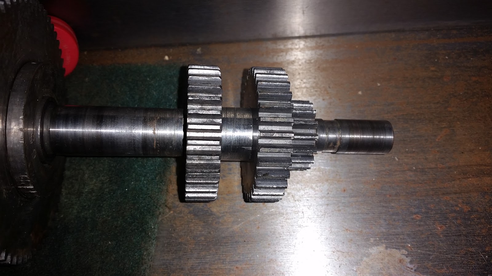
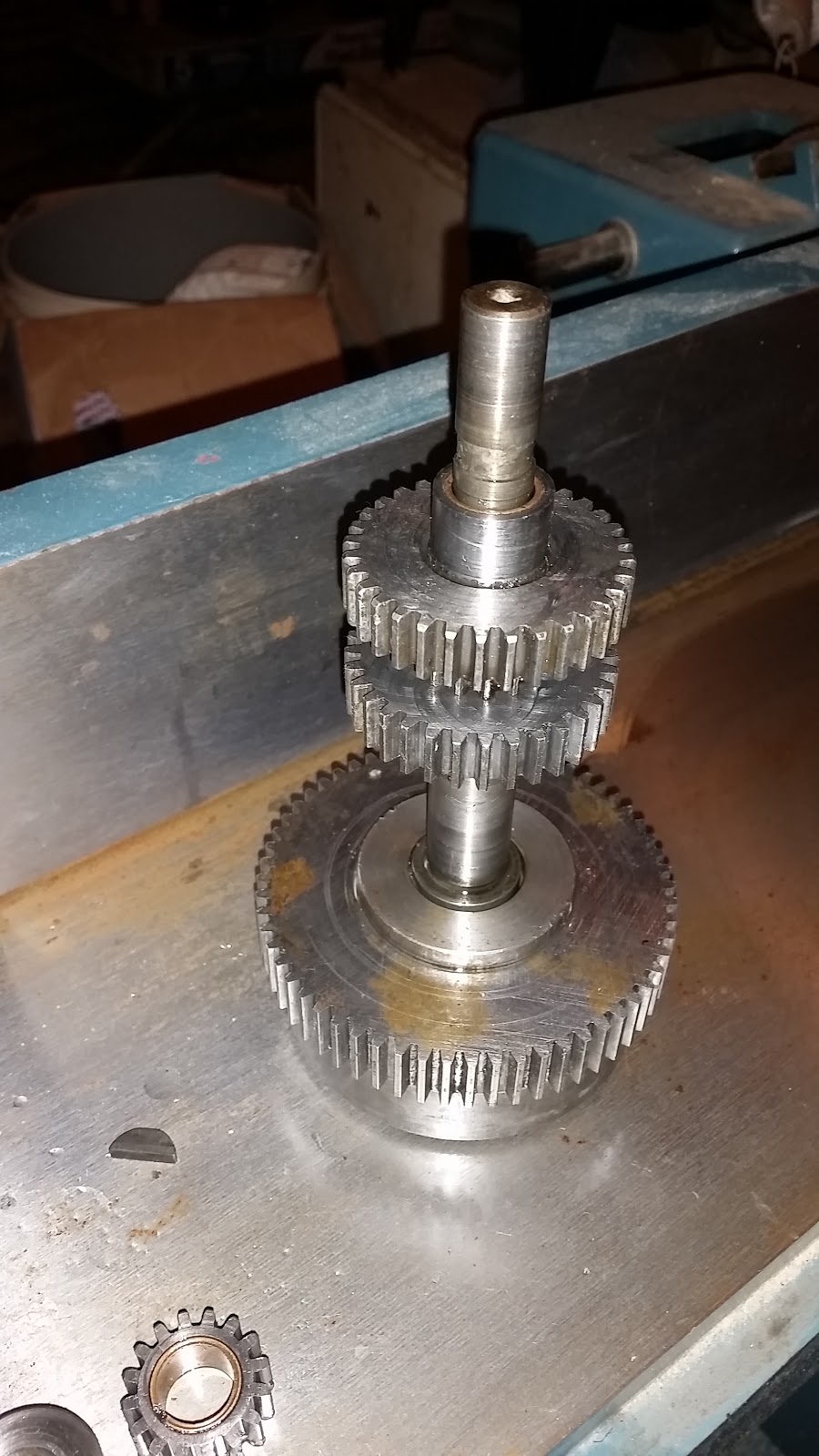
Now to the hard part.. reassembly of the gear train! As can be seen in the pictures below, there is not a lot of space to work! All those gears on the right there are KEYED to the shaft - and the key runs the entire distance of those gears!
I devised a scheme that I hoped would work to get those gears on the shaft without having to remove the bushing on the right hand side. The idea was to machine another shaft that I put the gears and key on and then run the actual shaft in from the left (it has to come in from the left - unless I also want to bore out the center bushing and replace that WHILE the shaft is in place - can't do it!). The actual shaft, of course, would have to be driven into the gears AND the key! This gave e an excuse to use my lathe to make a dummy shaft and use my mill to make a flat for the key! Fun! (it really was - lol)
 |
| Used my lathe to make a dummy shaft to help with gear train install. |
 |
| Got to use many of my lathe tools! |
 |
| And since I was turning a shaft, I got to use my live center! [BTW, I finally got a replacement nut for the tailstock handle so that's working nicely now] |
 |
| I saw a neat idea on youtube about making my own 60 degree center for my 3-jaw chuck to hold so that I didn't need to remove the chuck just to turn between centers! I milled an old bolt left over from previous owner. Carbide tooling cuts even that hard stuff! |
However, this "wonderful" dual-dummy shaft idea lead to my downfall. I was using a wooden mallet to drive the actual shaft onto the key and gears, but the fit was very tight. I decided I would "help" the fit by milling off some of the key height and width as well as filing some of the shaft so that the gears fit easier (the shaft was quite worn and had some creases in it that obstructed the gears from sliding on. I milled off so much of the key that it was able to fit inside of the center bushing/ This helped a lot because then I was able to have more room to fit the gears in place on the right hand side! However, When I got all of the gears on and everything seemed to be good - I discovered that the key was not engaging the gears near the center of the shaft! So I had to take it all apart again! Oh, but here is where things get really messed up - all of the gears came off easily - EXCEPT the ones near the center! The key got out of the key way (because it was so undersized) and WEDGED between the gears and the shaft. WEDGED tight! I tried using the mallet and even a hammer to remove them, but no go. I decided to give up at that point and left the farm before I could break something expensive!
My plan at this point is to try to drill out the key stock that is stuck between the gear and shaft. Then, hopefully that will loosen things up enough that I will be able to use the mallet to rive off the gears. Then I guess I will bite then bullet and bore out the bushing on the right side of the shaft and put the key in from that side (which I figure is how they assembled it to begin with). Of course that means I will need to get another bushing an press that in! UGH. Might be another month of work here!