gardening, self-sufficiency, homesteading, food preserves diary
Blog documenting progress in transforming new property (50 acres - mostly wooded) into garden-farmette . Trying to become more self-sufficient and more self-aware.
I got some new equipment in this week. New ER32 collet chuck, a spin indexer (with tail stock), a whole set of 5C collets for the spin-indexer, and a backplate to attach the collet chuck to the lathe. The backplate was for an 8" 3-jaw chuck but it had the correct spindle thread and size and it was a bargain at $36! So I figured I would just machine it down to size!
ER32 collet chuck. Only 100mm across. ER is a European standard so everything is metric on this chuck. This is the back of the chuck showing the registration depression and 3 threaded holes.
Here is the back plate on the lathe ready to machine! I didn't have to bore the hub this time - it just fit perfectly! Look closely and you can see the pencil mark showing the part of this backplate that I plan on keeping!
Here is the chuck held up to the backplate to get an idea of how much I would have to machine. Quite a bit!
Here I am with a cut-off tool making a deep groove in the plate. No reason to turn down all that material. I figured I would just cut through it!
Well, here is the thing.. The radius of this cut is tight enough to impeded the cutoff tool. So I had switch back and forth with a boring bar and the cut-off tool. It took a couple of hours to finally get through. Not to mention wearing one cut-off tool to the point where it will need to be reground!
Wooohooo! finally through! Just got to clean it up now.
Here it is with the registration hub all ready to go! I fit it damn near perfectly. The backplate and chuck match on this registration hub - no wiggle at all!
Side view.
The chuck test-fitted on the backplate! No Wiggles!
Closeup showing some defects in the casting! It worried me at first, but I think it will be ok.
I was having phone-battery issues again so I missed some of the pictures of hand-drilling the three holes into the backplate as well as pictures of removing the backplate using the old "bolt a piece of angle iron to the backplate and put it in reverse" trick! Sheesh! Those spindle threads really hold those things on!
Oh, and the joy of trying to hand drill the holes! I couldn't remove the backplate without having some kind of way of holding it. Therefore I had to drill the holes with the backplate in-place on the lathe spindle! Since the bolt holes in the chuck are metric, I had to go to the hardware store to get some M8-1.25x45mm screws.. They didn't have socket head screws - the only thing they had that would fit were hex-head bolts. I wanted the screws to feed through from the backplate to the chuck since the chuck already had the threaded holes. This approach was also best because it allowed me to drill (and file and generally mangle) the bolt holes oversized to give me wiggle room for my half-assed hand-drill job. I had to fiddle with the bolt holes for hours (it felt like it anyway). The holes look like crap and are sloppy as hell, but remember, the bolts are not what gives the chuck accuracy. The bolts are just to clamp the backplate to the chuck. The registration hub is what accuracy, and it fits perfectly!
The hex-head bolts in the backplate. I sharpened up one of the M8's that I got to use it as a center-transfer. That part worked fine. It was the sloppy hand-drill job that got me upset.
Looking at the back of the backplate here
See all of that space there around the bolt? Good thing the bolts are just for clamping and not alignment!
The chuck and backplate bolted together as best I can.
The hex-head bolts won't clear the hub of the backplate! Socket-head bolts will though. I ordered some nice socket-head M8-1.25x45mm from boltdepot. I hope to have them soon - I can't use this chuck until I get those bolts!
The next task was the cleanup of all of that damned iron-sand! UGH. I spent hours cleaning the lathe and vacuuming up all that crap! I noticed that quite a bit of the swarf got into the cross-feed screw compartment. I thought maybe that was what was causing a difficult to move feed.
On a side note, I tried using the powerfeed in high-gear and it made a HELL of a sound - I thought for sure that I had broken a gear. Thankfully, the sound I think is what the manual refers to as "clicking". The lathe has a safety feature to protect the gears when the powerfeed is overtaxed. Somehow the big gear that transfers power to the powerfeed box will "slip" thus protecting the gears from damage. I don't know how this works - maybe a big coiled spring or something?
In anycase, the cross-slide feed is hard as hell to turn. After cleaning and lubing it was still hard to move. So I decided to explore... I removed the cross slide feed handle and found that there are 3-spring loaded balls behind it! Fortunately, I didn't loose them! I did learn how to remove (some) slack in the cross-feed screw. I removed some, but not all. After the handle came off then I pulled out the dial. I needed a gear puller and as I was removing it from the cross-feed shaft I noticed that there was a bunch of gook on the gear of the cross-feed to powerfeed connection. I scraped it off and also filed some rust from the surfaces between the indicator dial and the hand dial. I cleaned everything with brake cleaner an even figured out a cleaver way of putting those balls back into the back of the feed handle! It moves a bit better now. I tried the powerfeed in high again and it didn't make the clicking sound and the feed stayed engaged. So thats something. Someday I will get the courage to dismantle the apron!
Spin-Indexer
I watched a video on youtube where a guy showed a spin-indexer that I thought would be useful in my shop. The indexer on ebay was very affordable. I got the indexer and tail stock for $88! Another youtube video shows a way of making index plates for a spin-indexer - so that might be a project down the road!
In the meantime, a little cleanup. One youtube video pointed out the utility of having the sides of the indexer trued up in order to make setup easier in some situations. Sounds like a good idea, especially for someone like me with no DRO or extravagant equipment.
Cheap Spin-indexer and tail-stock
Going to straighten up the sides of the indexer to provide more straight and flat surfaces to indicate off of during setups.
The face and bottom of the indexer are guarenteed flat and true. Holding it in the vise this way and using an indicator to be sure the faces are true to the spindle allows me to mill the painted edges off true.
I made a short YouTube video of the experience. I cut out the part where I made the mistake. I have to make a point (or make some notes) to use the mill more frequently so that I remember to check certain key points - like making sure the tool is seated in the collet correctly - and making sure that the collet is seated in the spindle correctly. Oh, and of course, making sure to use the dial gauges to make sure everything is true and flat and that the VISE IS TIGHTENED before making a cut!
Video showing the Van Norman 12 in operation!
Nice finish!
Trying to focus in on the flaw. Lower left corner. Someone didn't tighten the vise during one of the cuts...
As a boon, because I removed about 1/4"-5/8" off the width of this base, I am now able to mount the indexer in my table vise in either direction - which I wasn't able to before milling! Sweet!
Set-screw removal
I had been having trouble with a couple of set screws on the lathe last weekend. One was on a shaft in the powerfeed and the other was on the spindle handlewheel. I am not sure what the set screws are for on the handwheel - there are four of them and they seem to be holding in some springs. I got one out part way and could not get it to go back in all the way. After stripping the socket-head hex connector I had no recourse but to try a screw-extractor to get it out. I have never used a screw-extractor before - so it was an experience. I drilled out the screw and tried the extractor... MANY times. The extractor seemed to have a hard time engaging the screw. I finally drilled the entire way through the screw and THEN the extractor was able to grab! I got out the screw! YAY. It was a set-screw - 1/4"-20TPI .5 inch screw. I used a tap to chase the thread. Now just have to get another screw. Hmm - wonder what happened to the spring?
Tree-trimming
It was still very wet out in the fields but where the apple trees and grapes are was dry enough to get around. I trimmed all of the grapes and most of the apple and pear trees. I didn't do much with the peaches. I wasn't able to reach the tops to trim - I will have to go over them again with the pole trimmer. After trimming I plan to spray them all with dormant oil.
After I cleaned up most of the cast iron debris from fitting the new 4-jaw chuck, I decided to see what was up with most of the feed gears failing. After sliding the phone video camera into position under the quick change gear assembly and watching what was going on I figured out that a gear that shouldn't spin was spinning!
The inside of this gear is supposed to be pinned to the gear next to it. Those holes are supposed to have pins in them! This is just one of 3 of this type gear that I got off ebay to repair my quick-change gear box (needed for threading and powerfeed). Also, note how out of round the bushing is? This is partially due to it not being properly centered when I bored it, but it is also partially due to the fact that the shaft that this sits on is badly worn! I am going to replace that one shaft...
While it was heartbreaking to take apart the quick-change gear box again, there was no way around it. After removing the gearbox and disassembling it, I was able to remove the gear that failed.
The video shows the unpinned gear failure.
Re-pinning the gears
I was able to remove 2 of the gears that I got off ebay - the ones with the missing pins. The third is stuck on the drive shaft due to a stuck hex screw. I could drill out the screw, but then I would have to re-drill, and re-thread the shaft hub as well as find a hexhead screw to fit. Being Sunday, there is no way I would have this done this weekend. Furthermore, only one gear failed - I was able to remove the failed gear. So I left the one gear in place and focused on pinning the other 2. Even though only one gear failed, I figured while I had it out I might as well pin them both!
The one on the far left - next to the hub is the gear I cant remove - that hub is on there until I drill out the stuck hexhead screw.
Making the pins! Not having a lot of stock laying around, I decided to use an old burned and bent carriage bolt as the source for my pins!
Notice that I have the 3-jaw chuck on there now? I wanted to use the 4-jaw chuck, but the 4-jaw chuck doesn't close enough to grab this bolt!
Cut down to almost the size I need.
I got a couple of pins out of this one. I machined the bolt down to pin size a couple of times to get enough pins.
Just to keep things in perspective - the pin diameter is just under 1/8".
First pin in!
I simply used a hammer to seat the pins tightly (I drilled out the pin holes)
One down
Both done now. Now to cut them off flush with the surface
Cut and filed flush. Ready to install
Installed and ready to go - well - almost - I have to put the gear selectors on there yet!
The above video shows most of the gear assembly put back together and demonstrates how its supposed to work!
This video shows the gear assembly with the gear selectors in place and operating.
First Knurling!
I finally got everything cleaned up again and decided to actually use the lathe for something! I scanned around and saw that the side cover plate over the lathes backgears was attached with a hodge-podge of bolts, nuts and even one knurled nut. I decided that I like the knurled nut approach the best since that side panel would have to be accessible to put the lathe into backgear drive mode (at least for now - I am thinking of making something to help with that issue!).
Here is the one knurled nut that is used to attach the cover - the other attachments are with bolts or plain hex-nuts.
Hard to get a non-blurry picture of this thing!
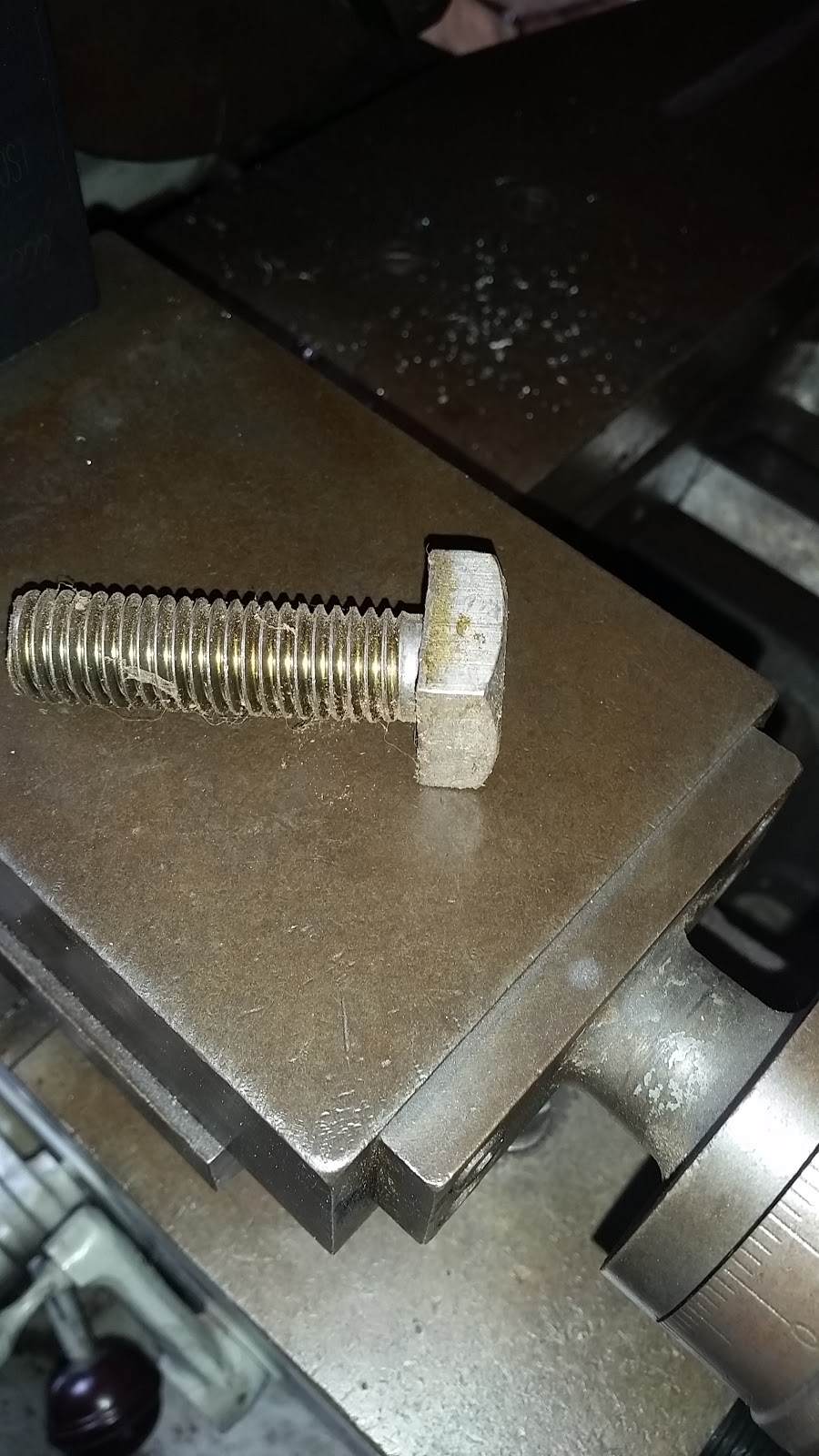
So I needed to find some stock that I could make this thing out of! I looked around the shop and found a box of these old tractor bolts - left over from previous owner. The tractor or implement that these fit is long gone I figure. I have used these for this type of things a lot lately! Anyway, I grabbed a bolt and started in!
These bolts machine quite nicely! I used one to make my bushing remover for the threading gears already.
OK, I should have taken more pictures throughout this process!
The bolt head was turned down to round and faced off. Then the shaft was cleaned of its threads and finally I used my knurling tool to knurl the head! Oh, and I drilled and tapped the threads - its a 1/4"-16 tpi.
The most difficult part was actually the tapping! I started tapping it in place as shown in the above pictures, but I wasn't sure the tapping chips weren't bunching up in the blind hole, so I tapped only about half way in and then cut the nut off the bolt shaft. Then I put the knurled end into the 3-jaw chuck and CAREFULLY tapped the rest of the way through. Even though I was careful I did get some marring on the knurled surface, but not too bad. I am seriously considering get a collet chuck for this lathe! An ER32 collet chuck is available on ebay and all I would have to do is machine up another back plate for it (and buy the collets of course). ER32 collets aren't expensive and are quite popular right now, so lots of accessories if I should need them (wrenches, collet caps, etc). [OK - I just ordered the ER32 chuck and backplate! and a set of ER32 collets!]
Burs all filed off and clean!
The other side. Could have cleaned the inside up a little more - but this is ok.
This stud used to have a plain hex-nut on it
Now it has a nice new knurled nut!
I think I like it better than the original! You can see the knurling "chattered" or double-struck a bit in that center section. This is due to the fact that I did'nt have the knurling tool centered on the axis of the turning piece when i started. I noticed it quickly and fixed it.
I am very happy with this! The knurling went surprisingly smooth. I did have a misalignment issue at first, but I corrected. Also, notice that I didn't push the full depth - this is fine as it is! I think I will make some more!
The real work to getting the chuck installed was really machining the backplate. I first bored out the lip of the hub so that it would fit onto the spindle head properly. Then I faced off almost a third of an inch from the hub to get it to engage the spindle threads. Then I put the backplate on "frontwise" - the way it will be used, and proceeded to face off the front and bring the registration boss to the correct dimension to fit the inside of the chuck. This registration boss had to be machined precisely to ensure the chuck would always mount true and run true to the backplate and hence the spindle. All this machining took most of a day and produced a lot of iron shavings - well really more like sand! What a mess!
TADA! The new chuck is installed!
View from the side. This chuck is screwed to the backplate form the front.
"Iron sand" from the machining of cast iron!
This stuff is everywhere!
I tried to keep it contained, but it still got everywhere!
This is the little that I was able to collect. The rest got vacuumed up or wiped up when I cleaned later.